When conducting your thermal testing, it is important to know that there is a difference between the temperature of the mounting surface versus the temperature of the conductors inside the heater itself.
For example, if you are mounting a heater onto an aluminum plate and you want the aluminum plate to reach, say, 300°F, you likely will have the heater power up higher than 300°F so that it doesn’t take a long time for the plate to warm up. (The more extra power you use, the faster it will warm up.) Eventually, the heater and the plate stabilize at generally the same temperature, whether you control the heater or not. During this temp rise cycle, if you measure the aluminum plate and it says 300°, the conductors within the heater may be, for example, 350° because the heat not only goes into the aluminum plate, the heat also dissipates out the other side of the heater. If the heater is mounted ‘open face’ and is exposed to the air on the non-mounting surface side, that extra heat dissipates into the surrounding air.
However, air is not a great conductor – not nearly as conductive as the mounted surface side where the heat transfers into the mounting plate quickly due to its direct contact with the plate. Instead, the heat on the air side doesn’t exit from the heater as fast, further driving up the temperature of the conductor strands themselves, while becoming a contributing factor to the heater overheating.
Notably, it is the temperature of the individual heater strands within the heater itself that defines the limit of the heater, not the temperature of the plate.
The breakdown of the heater occurs when the temperature of the internal bonding adhesives holding the heater layers together exceeds the bonding adhesive’s temperature limits – and they delaminate. Specifically, it is the internal bond layers on both sides of the conductor that experience the highest temperature exposure. The foil conductor strands don’t fail because they are metal and won’t melt at anywhere close to this temperature. The insulative films (Teflon, fiberglass, polyimide) have high melt points so they, too, remain in-tact and perform insulating function.
The delamination that occurs within the heater causes the heater strands to lose contact with the mounting surface, creating an air gap between the plate and the heater strand. The result is that the heater strands no longer conduct quickly into the aluminum plate and the heat within the heater starts to rise. The heat builds and eventually things overheat, the surrounding encasement becomes brittle, the foil itself changes its metallurgical properties, thermal expansion takes place, and the combination of all of this causes burnout.
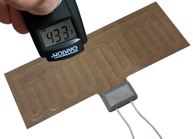
In reality, the thermal limit of the heater can be determined using an alternative method, such as this approach used in evaluating TurboFlex Teflon Fiberglass heaters. The true survival temperature of Teflon heaters can be determined by performing the opposite scenario. Instead of the heaters being powered and driving the heat generation, the aluminum mounting surface was raised to 450° through other means. The heater was passive and not powered, thus taking that influence out of the equation. In this method, the heaters are exposed to an accurate temperature throughout the body of the heater, and the testing confirms survival (no mechanical delamination) to 450° and higher. This way we know that the conductive strands were not experiencing a higher temperature than what the apparatus indicates.
Can the Heater Handle Higher Watt Densities?

In a general perspective, flexible heaters are commonly rated by watt density limits. Although this gives a decent indication, the watt density limit completely depends upon the customer’s application and if the product design is able to keep the heat within the heater below the bonding adhesive’s mechanical threshold. This will be due to factors that contribute to getting the heat out of the heater. Interestingly, we have successfully used heaters with more than 75 w/in² watt density – a remarkably high value. These heaters were compressed between plates and the assembly was driving thermal shock tests from -40° to +100°C. The watt density and wattage were high, but the heater itself never approached its thermal limit. Furthermore, since the heater was mechanically squeezed between two thick plates, there was not an opportunity for delamination to occur even if the adhesive broke down because the plates held the layers in-tact. The insulative properties of the film will remain whether the adhesive lost its adhesion characteristics or not.
So, although watt density limits provide a guideline, customers should perform thermal tests with their particular design/package to understand where the thermal limit is.
Silicone Rubber
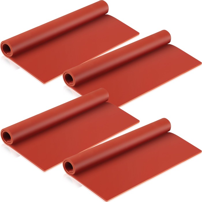
Silicone Rubber heaters are typically rated higher than traditional polyimide heaters but they, too, can experience thermal failure due to overheating. The same issue exists where excess heat builds up within the internal layers of the heater.
This would be due to a couple factors:
- Losing contact with the mounting surface.
The peel-and-stick adhesive pre-mounted on the back of the silicone rubber is just not as strong as PSAs that adhere foil heaters constructed of polyimide films. It’s likely that the weak link is not the adhesion to the plate , its adhesion of the PSA against the silicone rubber surface that lets loose. The SR just doesn’t provide as strong of bonding interface with its own mounting adhesive. This is why many SR heaters are pre-mounted against their mounting surface/plate at the heater manufacturer’s factory – where the uncured rubber heater is vulcanized to the plate rather than using a separate bonding adhesive to mount it.
Particularly evident when mounting onto a curved surface, the thickness of the silicone rubber introduces an inherent mechanical tension to want to return to its flat state. This essentially creates a continuous tensile force pulling itself off the curved surface – further contributing to the adhesion potential to delaminate off the plate throughout temperature swings.
2. The thermally insulative properties of the silicone rubber.
As mentioned earlier, conducting the heat from the heating element into the mounting surface is very important. Silicone rubber is not only much thicker than plastic films, (4X to 10X thicker), the SR material itself is significantly more thermally-insulative than these films. The result is that the heat can’t transfer as quickly, and therefore the element itself retains more heat. And similarly, on the opposite “open-face” side that is exposed to the air, the heat can’t dissipate into the surrounding air as quickly as well.
Countering this effect is that that rubber is a higher thermally-rated material than the bonding adhesives within a traditional polyimide heater.
Combined, these aspects are likely the root cause of over heating failures of Silicone Rubber heaters, resulting in the generation of hot spots within the heater which cause failure. This is independent of the likelihood that the silicone rubber heaters may have rugged, long lasting wire-based conductive strands within it.
Conclusion
Although heat generation is the functional purpose of flexible heaters, customers of flex heaters need to understand that the heaters can deliver a substantial amount of wattage/heat – much more than the heater itself can handle. They have little mass and are not designed to retain heat.
Yet in these high temperature applications, they can survive and can be highly reliable – provided the heat they generate is quickly pulled out of the heater and into the surroundings – through conduction.